BrooksBots

RoboMagellan

FireBall

Videos

ExSpurt

ExSpurt Tires

ExSpurt Strategy

Executioner

Extrasensory II

Expressway

Extrasensory

Excuse II

75 lbs Sumo

Excuse

Expendable

Exhume

Mighty Man

Sticky

Flaming P'nut

Exert-O'Meter

Runt

Wall Follower

SPAR Videos

Wall Follower

SME Wall FollowingRichey's wall following robot has won the RI/SME and Ohio Tech National Robotics Challenge Non-tactile maze competition from 2001 through 2004. The robot is based on the Parallax BOE-Bot and uses the distance detection technique as described in the Robotics with the BOE-Bot Student Guide. The user should review this documentation and complete all of the exercises in the guide as a prerequisite to beginning construction and setup of a wall follower. Listed below are the details of Richey's champion wall follower.

Side ViewConcept The wall follower uses two IR LED/Detectors. One of the IR LED/Detectors measures the distance to the left wall and the other IR LED/Detector measures the distance to the front wall (if the front wall is close). In an effort to anticipate corners, the left IR LED/Detector was angled 45 degrees forward. The BS2SX was used in place of the original BS2 because of its more accurate generation of the frequencies required to fire the IR Bottom ViewLEDs. The original servos were replaced with Hitec HS925MG servos to increase speed. Also, the servo electronics were replaced with external H bridges to further increase performance. The competition requires the robot to climb a ramp from the lower level maze to the upper level maze. Tires molded out of silicone were used to help in the climb up the slippery, dusty ramp.

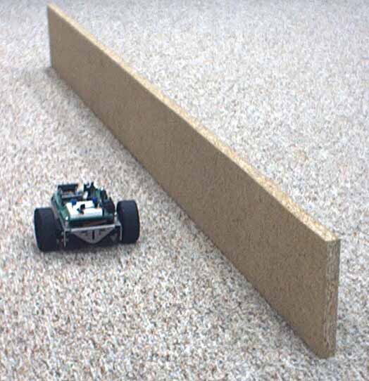
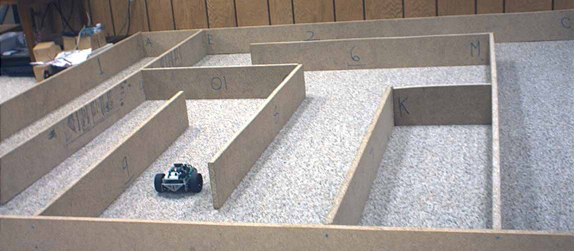
Sensors Selecting the frequencies for the distance detection is the most critical phase of the project. The frequencies must be determined for each IR LED/Detector combination. If either the IR LED or the detector is replaced, then a new set of frequencies must be determined.

A frequency sweep was done for each inch from zero inches until there was no contact at any of the frequencies. The sweep was done from 32,500 Hz to 38,750 Hz with 25 Hz steps. At each frequency, an attempt to get contact was performed ten times and the number of hits was recorded. A little math indicates that we are looking at 50,000 to 70,000 individual tests for the sensors. A little intimidating, isn't it?

First, a program was written to make ten attempts to detect an object and the number of hits was printed along with the frequency. Then the program was modified to run from 32,500 Hz to 38,750 Hz with 25 Hz steps. That gives us this very long printout. Using StampDAQ the printout can be captured and pasted in an Excel spreadsheet. The data was manipulated by Excel to find the best frequency for each distance.

Two IR Sensors on BOEElectronics The fixed resistors that limit the current in the IR LEDs were replaced with adjustable 5K Ohm pots to allow for varying lighting conditions at the events. A red/green LED was added to indicate with sensor (front or side) was controlling the robots movement.

Program Logic A program was written to follow the left wall. If the wall was a few inches away, then the robot would go straight. If the wall was a little closer, then the robot would turn a little to the right. If the wall was a little farther away, then the robot would turn a little to the left. The closer or farther away from the wall would produce sharper turns. There are five increments of distance from the wall that determine the rate of turn.

The same logic applies to the front sensor. If the front sensor doesn't see anything, then the left sensor controls the direction of travel. If the front sensor sees something, then the robot turns right. The closer that the robot gets to the front wall, the harder it turns. Using this logic is OK, but one problem was encountered. While turning around the end of a left hand wall, occasionally the front sensor would see the far wall and command a right hand turn. This is not acceptable. So, one more step was added. If the left sensor did not see anything, then the front sensor was ignored and a hard left turn was commanded.

Simple Maze TestDetails Setting up the correct angle and distance of the sensors proved to be very challenging. First, one board was attempted. Using just the left sensor for direction, the robot was adjusted to follow the board smoothly and perform the left hand turn at the ends. Once the robot can follow one board without touching, then a second board was added as a "T". The front sensor was adjusted to properly react to the "T.

Lower Level of the MazeThe lower level of the maze was constructed. The final fine tuning at home was done on this maze. Once properly adjusted, the robot would follow the maze to the end, do a 180 degree turn and return to the beginning. Then another 180 degree turn and the robot would rerun the maze. This would continue until the batteries died.

Contest Before each contest, the maze following robot could run the home course perfectly. Lighting and traction differences at the contests each year required hours of fine tuning the day before the event at the event site on the actual maze. Some times the previous days setup would not work for the contest. There is a lot of fine tuning to be done to produce a successful maze following robot.